Subscribe:

Ads 468x60px

Sunday, 22 May 2011

Simple UPS


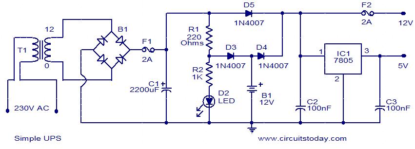
This is the circuit diagram of a simple UPS that can deliver 12V unregulated and 5V regulated DC. The transformer T1 steps down the mains voltage to 12V AC and then the bridge B1 rectifies it. The rectified signal is smoothed by the capacitor C1.When the mains supply is available the battery will be charged via diode D3 and the regulator IC gets supply via diode D5. 12V and 5V DC will be available at the output terminals. When mains supply is not available the battery supplies current to the regulator IC and to the 12V DC terminal through diode D4.Also, the diode D3 blocks reverse flow of current during battery mode. Capacitors C2 and C3 acts as filters.
Circuit diagram with Parts list.
simple-ups-circuit
Notes.
  • Assemble the circuit on a good quality PCB.
  • The transformer T1 can be a 230V AC primary, 12V secondary,3A step-down transformer.
  • The bridge B1 can be a 2A bridge. If such a bridge is not available, make one using four 1N4007 diodes.
  • The capacitor C1 must be rated at least 25V.


Read more: http://www.circuitstoday.com/category/ups#ixzz1N9O87QEK
Under Creative Commons License: Attribution

UPS-Uninterruptable Power Supplies

Most of us take the mains ac supply for granted and use it almost casually without giving the slightest thought to its inherent shortcomings and the danger posed to sophisticated and sensitive electronic instruments/equipments. For ordinary household appliances such as incandencent lamps, tubes, fans, TV and fridge, the mains ac supply does not make much difference, but when used for computers, medical equipments and telecommunica¬tion systems, a clean, stable interruption free power supply is of the utmost importance. Of the myriad of devices, processes and systems which rely on ac power, computers are probably the most sensitive to power disturbances and failures. Interruptions in power supply may cause the contents of a memory to be lost or corrupted, the entire system to malfunction or fail, or even variety of components failures to occur, all of which not only result in inconvenience but also loss of money.
As more and more PCs, word processors and data terminals find their way into small business, UPS systems that meet the power requirements and price range needs of even the small business organizations and offices are being manufactured.

Uninterruptible Power Supply Systems.

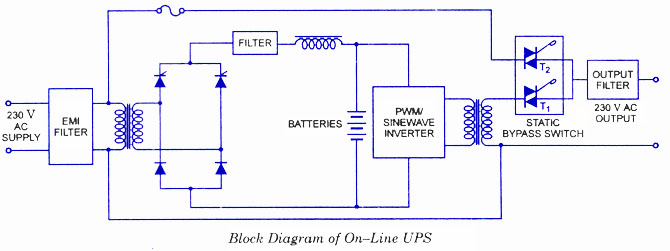
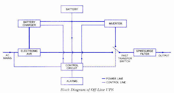
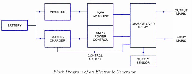
There are three distinct types of uninter­rupted power supplies, namely, (£) on-line UPS (ii) off-line UPS, and (Hi) electronic gen­erators. In the on-line UPS, whether the mains power is on or off, the battery operated inverter is on all the time and supplies the ac output voltage. When the mains power supply goes off, the UPS will be on only until the battery gets discharged. When the main power resumes, the battery will get charged again. In off-line UPS and electronic genera­tors, ther inverter is off when the mains power is present and the output voltage derived directly from the mains is the same as the mains supply voltage. The inverter turns on only when the mains supply goes off.
The block diagrams of on-line UPS, off-line UPS and electronic generators are given in figs
The ever increasing importance of computers in industry and commerce will increase the need for quality, high stability and interruption free power supplies.
A clean ac power source is the fundamental to the operation of most sensitive elec­tronic equipment, and many new and sophisticated circuits are designed to overcome the effects of disturbances normally found in the mains ac supply.
In order to protect a sensitive system from power losses and blackouts, an alternative power source is required that can switch into operation immediately when disruption occurs. An interruptible power supply (UPS) is just such an alternative source. A UPS generally consists of a rectifier, battery charger, a battery bank and inverter circuit which converts the commercial ac input into dc suitable for input to the battery bank and the inverter. The rectifier should have its input protected and should be capable of supplying power to the inverter when the commercial supply is either slightly below the normal voltage or slightly above.

Online UPS:


Online UPS Block Diagram
In case of On-line UPS, the battery operated inverter works continuously whether the mains supply is present or not. Triac T1 is on for all the times while Triac T2 has been provided to bypass the UPS inverter, only when a fault develops in the UPS inverter. When the mains supply fails, the UPS supplies power only until the batteries get dis­charged. However, once the mains power resumes, the batteries will get charged again. The switching times of these supplies is considered to be zero. Usually sealed maintenance free batteries are used and the running time of the inverter is low (approximately 10 to 30 minutes).

Off Line UPS:


Offline UPS Block Diagram
In the case of Off-Line UPS, the inverter is off when the mains power is on and the output voltage is derived directly from the mains. The inverter turns on only when the mains supply fails. Its switching time is less than 5 ms. These UPS are generally used with PCs or computers or other appliances where a small duration (5 ms or less) interrup­tion in power supply can be tolerated. Usually, sealed batteries or lead-acid batteries are used. The running time of these supplies is also low (about 10 to 30 minutes).

Electronic Generators:


Electronic Generator
An electronic generator is the same as the off-line UPS system except for one difference that switching time from the mains supply to battery driven inverter supply will not be small (over 10 ms) for the electronic generator. Also, the electronic generators will run for longer time (1 to 4 hours) than off-line UPS systems because, usually large size lead-acid batteries are used with/electronic generators. These are meant for household applications to run fans, coolers, fridge, lights, TV and VCR.
The demand is the highest for the electronic generators meant for house hold applica­tions, followed by the off-line UPS, and then the on-line UPS systems. The off-line or on­line UPS systems are mainly used in places where PCs or computers are used. The de­mand for on-line UPS systems is less than for off-line UPS systems because the price of the on-line UPS systems is higher.


Read more: http://www.circuitstoday.com/category/ups#ixzz1N9Nujfrl
Under Creative Commons License: Attribution

2 km FM transmitter


Description.
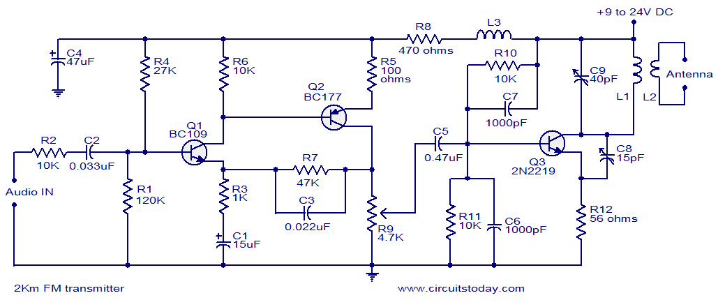
With a matching antenna, the FM transmitter circuit shown here can transmit signals up to a range of 2 kilo meters. The transistor Q1 and Q2 forms a classic high sensitive preamplifier stage. The audio signal to be transmitted is coupled to the base of Q1 through capacitor C2. R1, R3, R4, R6, R5 and R9 are the biasing resistors for the preamplifier stage comprising of Q1 and Q2. Transistor Q3 performs the collective job of oscillator, mixer and final power amplifier.C9 and L1 forms the tank circuit which is essential for creating oscillations. Inductor L2 couples the FM signal to the antenna.
Circuit diagram.
2km Fm transmitter
Notes.
  • Assemble the circuit on a good quality PCB.
  • The circuit can be powered from anything between 9 to 24V DC.
  • Inductor L3 can be a VK220J type RFC.
  • For L1 make 3 turns of 1mm enamelled copper wire on a 10mm diameter plastic former. On the same core make 2 turns of 1 mm enamelled copper wire close to L1 and that will be L2.
  • Frequency can be adjusted by varying C9.
  • R9 can be used to adjust the gain.
  • For optimum performance, value of C8 must be also adjusted.
  • Using a battery for powering the circuit will reduce noise.


Read more: http://www.circuitstoday.com/2-km-fm-transmitter#ixzz1N9N8aodP
Under Creative Commons License: Attribution

Gas Discharge Tubes (GDT) – Introduction


GDT’s are special type of gas filled tubes used for wide range of electronic/electrical circuits for providing protection against lightning and other power surges.  These tubes basically has two electrodes that are kept inside a gas filled closed envelope. In case of electronic applications, the container is mostly ceramic in nature. For high grade electrical applications military tubes are used. The electrical characteristics of this tubes depends on the pressure and composition of gas, and the distance between the two electrodes contained inside. The most commonly used gases in GDT’s are given below.

1) Hydrogen gases
2) Deuterium gases
3) Noble gases
4) Elemental vapors (metals and nonmetals)
5) Other gases
6) Insulating gases
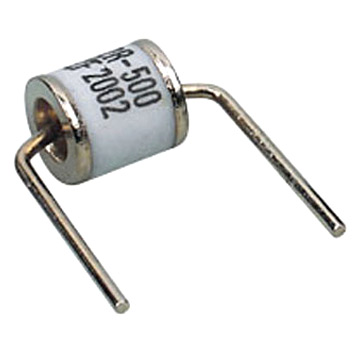
An image of a ceramic discharge tube is shown below. Take a look.

Ceramic Discharge Tube
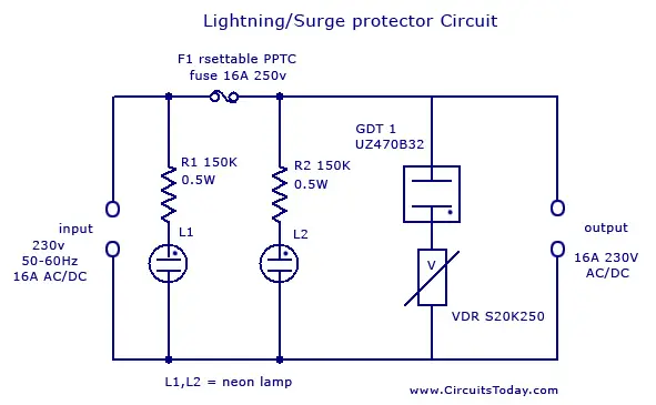
There will be conduction inside the GDT’s due to ionization of gas molecules. Each GDT have a specific voltage and current rating. A simple lightning protector circuit is given below.

Lighting/Surge Protector Circuit

In power lines, usually large amount of voltage is induced (typically very short time with high amplitude) due to lightning (direct or indirect strike) or Transients*
* (Transients caused by other equipments are usually caused by the discharge of stored energy in inductive and capacitive components. Electric motors, such as those used in elevators, heating, air conditioning, refrigeration or other inductive loads, can create a continuous stream of 250V to 1000V transients. DC motor drives, variable speed AC motor drives, DC power supply switching, and portable power tools are other sources of transients.)

Lightning Protector Circuit
The basic surge suppression circuit shown below consists of a VDR** (Voltage Dependent Resistor) and gas surge suppressor (GDT) connected in series. The protection circuit is connected between live and mains lead. Normally no current flows through GDT and VDR1. When   the voltage between the terminals is higher than the sum of voltage ratings of GDT and VDR1 (here both GDT UZ470B and VDR S20K250 has 250v 16A rating), current starts to flow through those components. If more the voltage rises then more current starts to flow through GDT and VDR1.When the current is normal, the circuit is reset and resumes it’s functioning. Thus the current cannot be raised much over that predetermined value. When the voltage again goes back to normal values G1 and VDR1, the conducting stops and the circuit remains normal.  If the flowing current is more than the specified value of main self-resettable fuse, the fuse will break and the circuit will be protected. After the current is normal, the fuses resets and continue its functioning (protection against short circuit and overload). The circuit is designed to protect sensitive electronic devices against overvoltage transients in normal mains voltage and overload/ short circuit. Two neon pilot lamps are also provided with the circuit diagram to show the status of input and load supply.
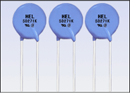
(**A VDR (Voltage Dependent Resistor) is an electronic component with a “diode-like” nonlinear current–voltage characteristic. The name is a portmanteau of variable resistor.  VDRs are often used to protect circuits against excessive transient voltages by incorporating them into the circuit in such a way that, when triggered, they will shunt the current created by the high voltage away from the sensitive components. A VDR is also known as Voltage Dependent Resistor or VDR. A VDR’s function is to conduct significantly increased current when voltage is excessive.)

Voltage Dependent Resistor

Advantages

1)      Normal working voltage = 230v AC/DC
2)      Maximum current rating=16A
3)      Cut-off current =16A
4)      Cut-off voltage= >300v R.M.S
5)      Protection against overloads
6)      Protection for short circuit

Applications

1)      Protection for sensitive components
2)      Protection for motor devices
3)      Telephone line protection
4)      SMPS protection


Read more: http://www.circuitstoday.com/#ixzz1N9Mirr3w
Under Creative Commons License: Attribution

mobile car hack


We have always been scared about our mobiles and computers getting hacked. Now it is time to know that there will be a time in the near future where people can easily hack cars. The car designs are becoming more and more sophisticated and you can also notice the change of simple mechanical automobile designs to a sophisticated network which includes almost 70 computers, collectively called Electronic control Units (ECU’s). All these computers are connected to each other and also to the internet.

Car Hack
Car Hack
Through these inter-connections, the car becomes a small data center that can be affected by many types of digital hacks similar to that of a mobile and computer. Some of the most common hazards are viruses, denial of services and so on.
The Electronic Control Units can manage most of the real time systems of cars like the steering, infotainment console, all lights, ignition, and crash bags and so on. For this to work software’s are developed that has millions of lines coded to make the ECU do a specific operation at a specific time. As the networks can be shared through long distances, more common gadgets like GPS and MP3 players can be easily controlled. But, there may arise technical difficulties when some nonessential components and infotainment share the same network with the brakes, steering and other main devices.
So how can all this be useful to a hacker?
He can easily open the car lock and start the vehicle from a distance with the help of a cell phone and get inside the car and drive away. A similar test was done by two professors named Stefan Savage and Tadayoshi Kohno at the National Academies Committee on Electronic Vehicle Controls and Unintended Acceleration. They inserted malicious software inside the car’s software system using its Bluetooth and mobile phone connections.
Thus it is time to implement counter safety measures from these unethical hacks. Or else, the wireless communication will be easily jammed, relayed or even broke down.
The counter safety measures are already being studied by the E-Safety Vehicle Intrusion Protected Applications (EVITA) project headed by Olaf Henniger, a researcher at Fraunhofer Institute for Secure Information Technology – Germany. The main aim behind the project is to more secure onboard networks in cars. Apart from this special methods are being developed to protect the vehicle to vehicle and vehicle to infrastructure communication so that accidents can be avoided. Many prototypes have already been developed but have turned out to be very expensive.
Some companies like Ford have already installed their own security measures that were developed by Microsoft. According to them, their car is safe enough from all alien network attacks. They have installed special firewall that can withstand any type of hacking.
There are various mobile applications that are available in the internet with which the car ignition can be remotely started. Also other functions like steering control, infotainment network control, and also door unlock control can easily be obtained. The mobile becomes paired with the car through Bluetooth. If a person is able to get control of the phone (perhaps through a virus downloaded from the Web), that person might then be able to gain access to the vehicle to which the phone is paired.


Read more: http://www.circuitstoday.com/#ixzz1N9MPODkf
Under Creative Commons License: Attribution

Multi-Channel Surround Sound Systems- frm circuit today


Multi-channel Audio

Multi-channel audio systems are widely used in modern sound devices. The term “multi-channel audio” means that, the audio system can be capable of handling multiple audio channels (usually called audio tracks) to rebuild the sound on a multi-speaker setup.
Usually two digits separated by a decimal (.) point (2.1, 4.1, 5.1, 6.1, 7.1, etc.) are used to classify the various kinds of speaker set-up, this number basically depending on how many audio tracks are used. Some audio systems only have a single channel (called monophonic sound or single channel audio) or two channels (stereophonic sound or 2.0 channel sound)
The first digit shows the number of primary channels (called satellite units), each of which are reproduced on a single speaker (these speakers are capable for handling the frequency range from 100Hz to 22Khz), while the second (decimal digit) refers to the presence of LFE (Low Frequency Effect), which is reproduced on a subwoofer.

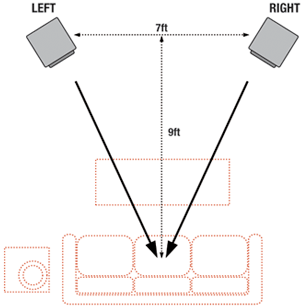
Stereo Setup
Stereo Setup
Surround Sound System
Surround sound is a term used to describe a type of audio output in which the sound appears to “surround the listener” by 360 degrees –  that is, the technology gives the impression that sounds are coming from all possible directions.
Surround sound is a way to provide a more realistic and engaging experience. All technical aspects aside, surround sound works because multiple audio channels are received through speakers that are positioned at various locations in the room. This is programmed into the source and the sound tracks are decoded when the source is played.

The Surround Sound Setup

The main component of a surround sound setup is a multi channel or digital coaxial/optical audio decoder. Using a DVD/HVD movie, the audio is encoded when the DVD/HVD is produced by packing multiple audio channels into a compressed format for storage.  When you play the DVD movie, your DVD player or A/V receiver (commonly called a home theatre receiver) decodes the encoding scheme (i.e. Dolby Pro Logic II or DTS for example). Decoding capabilities of an A/V receiver are built in. Most A/V receivers today can decode Dolby Digital and Digital Theater Sound (DTS) (DTS channel usually a coaxial or optical audio channel. It is a single channel digital pin that multiplexed with several channel. The decoder decodes the DTS sound from single channel to multiple channels), while higher-end receivers may also include DTS-ES or THX Surround.

Multi-channel Surround Sound Systems

  • 5.1 Surround Sound Systems
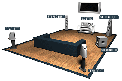
5.1 Surround sound systems are one of the widely used surround sound setup in home theater systems. Usually- Dolby Digital and DTS encoded in a DVD are 5.1 channel audio formats.  5.1 surround sound technologies produces five channels of sound in the left, right, center, left-surround and right-surround positions. These five channels are the minimum required to produce 5.1 surround sounds. The dot decimal (.1) represents the channel for LFE (low frequency effects), which is usually sent to a subwoofer. Other 5 units are capable for handling the frequency range except low frequency(Usually they are capable of  handling  the frequency range from 100Hz to 22Khz and no need for any other higher frequency component like tweeter). These five units are usually called satellite units. The arrangements of a 5.1 surround sound setup shown in the picture below.

5.1 surround sound
5.1 surround sound
  • 6.1 Surround Sound Systems
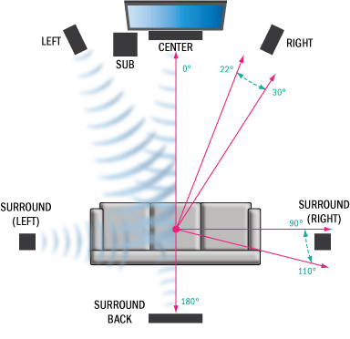
6.1 multichannel sound technologies is the advanced version of 5.1 surround sound technology. 6.1 technology uses the same set-up as a 5.1 system, but it has the addition of a sixth speaker that takes the rear-center surround position (or back surround position) to provide a more 3-D realistic surround sound effect. 6.1 surround sound uses extended surround sound formats, such as THX Surround EX, Dolby digital ES and DTS-ES. The 6.1 channel surround sound setup is shown in the picture.

6.1 Surround Sound Systems
  • 7.1 Surround Sound Systems
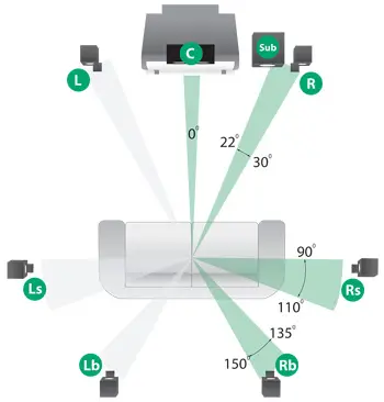
7.1 channel audio systems is the modified version of 6.1 channel and also provide more realistic experience than 6.1 setup. In this system splits the single rear-center speaker into individual left- and right-rear surround. These systems are not a true discrete 7.1 channel system as 7.1 formats don’t currently exist. In a true discrete 6.1 surround system, the back center surround position is separate from the surround left (SL) and surround right (SR) positions. A 7.1 channel system uses   matrixes extended surround where the left-back and right-back (rear-center surround) multichannel are blended together and stored. The structure of a 7.1 setup is given in the Picture below.

7.1 Surround Sound Systems
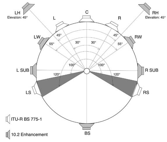
  • 10.2 Surround Sound Systems
10.2 channel surround is the future surround sound technology that Developed by THX corporation, the name itself, 10.2 is an advanced version of 5.1 technology but 10.2 is twice as good as 5.1. In a 10.2 surround sound 14 channels are used. This includes five front speakers, five surround channels, two LFE and two heights, plus the addition of a second sub-woofer. This technology is considered as future TRUEHD.The Diagram of a 10.2 TrueHD setup is shown below.

10.2 Surround Sound Systems

Common Surround Sound Formats

  • Dolby Surround
Dolby surround is the consumer version of Dolby analog film decoding. This technology was introduced in 1982 which is capable of handling stereo and hi-fi audio. This audio format is commonly found in VHS and stereo hi-fi systems. In this surround format, the multichannel audio multiplexed into two audio channels (left and right channels)and decoded by using Dolby pro logic decoder ,then it recreates the four channel Dolby surround experience.
  • Dolby Digital
Dolby digital is the standard surround sound format which provides high quality and highly realistic experience. This audio is developed by Dolby Corporation. Dolby digital audio is also known as Audio Codec-3(AC3). This audio format provides a high quality 5.1 surround experience. Normally this audio format used for the creation of DVD and Blue ray movies. Some video games and play station units are also available in this surround sound format.
  • Dolby Digital EX
Dolby Digital EX is the modified version of Dolby digital audio. This extended format contains an additional surround sound unit (called center surround channel) for creation of more realistic experience. Dolby digital EX needs Dolby EX decoder. This surround effect also support 5.1, 6.1, 7.1 channel playback. This audio format usually available on DVD, HVD, blue ray, play stations, DTV broadcasts, etc .
  • Dolby Pro Logic IIx
Dolby Pro Logic IIx is an advanced version of Dolby Digital EX technology. By using this technology, we can expand the 5.1 channel Dolby surround system into 6.1, 7.1, 10.2 channel surround. The Dolby digital prologic usually use three modes for listening (movie, music and game modes).This surround technology provide more rich  and depth surround sound effect   than conventional surround sound system. This audio is normally encoded in DVD, HVD, BRD HDTV, play stations,  etc.
  • Dolby True HD
Dolby True HD surround sound is an advanced version surround sound that provides incredible High Definition experience to the listener. This surround sound format is also known as next generation surround sound format. Dolby True HD format only support HD based media and this technology provides 100% lossless audio encoding, bit rate up to 18Mbps and support 8.1 or higher channel with 24 bit/96Khz audio. This format also supports HDMI. Normally BRD and HVD are used for encoding this true surround.
  • DTS
DTS is another digital surround format developed by DTS Corporation. It is a Multichannel digital surround format widely used in both consumer and commercial applications. The DTS audio system must have a DTS decoder and optical/coaxial digital decoder for decoding this surround. DTS is normally available in a single channel multiplexed format (2.1 to 11.1 channel surround sounds can be multiplexed into a single optical digital or coaxial output format).DTS format  is also available on DVD,HVD and BRD’s.
  • DTS-ES
DTS-ES (digital theater sound –Extended Surround) is an advanced version of normal DTS. This surround system is usually available in 6.1 or higher channels. This provides us with more true digital experience than conventional DTS system. This unit also requires an additional DTS-ES decoder for the creation of a back-surround effect. The system is compatible with all current extended surround formats and an auxiliary surround channel is also provided for other applications.
  • TruSurround-XT
TruSurround XT is the next generation of SRS TruSurround. The main advantage of this surround system is that it’s capable of handling 2.1 channel surround to 10.2 channel surround (support head phone media too).Audio is encoded in multiplexed format. and require DTS true surround decoder. This audio usually encoded in BRD’s and HVD’s


Read more: http://www.circuitstoday.com/#ixzz1N9LzTlIU
Under Creative Commons License: Attribution